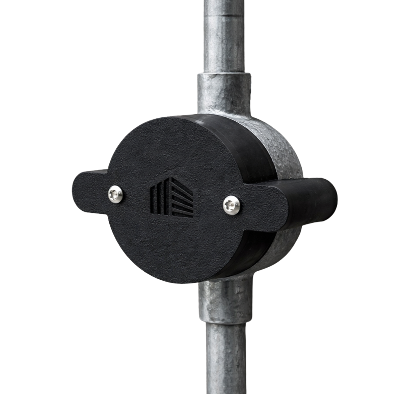
Model T8-HSJB-STD · Everything on the in-box installation sheet, plus downloads, the independent test report and support.
Not supplied: a standard 20 mm or 25 mm BESA-type conduit box, securely fixed at all points · wall plugs to suit the substrate · alarm cable · Tier8 HSJB drill template (sold separately – free with your first order).
Tools: drill and bit to suit the wall plugs and building fabric · Pozi/Phillips screwdriver · T20 6-lobe pin security driver.

Fit the drill template to the conduit box using the two M4 standoffs. Mark and drill the two fixing holes through the template legs, sized for the wall plugs and substrate.
Remove the template. Fit wall plugs to suit the substrate, flush to the wall.

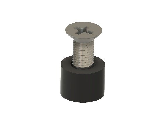
Slide a 5 mm collar onto each 3.5 × 40 mm screw (7 mm collar if using the leg extensions – see below).
Drive each screw until the head seats on the collar. The collar sets the height; the countersunk head gives depth tolerance. Do not overdrive.

Bring the alarm cable into the conduit box.
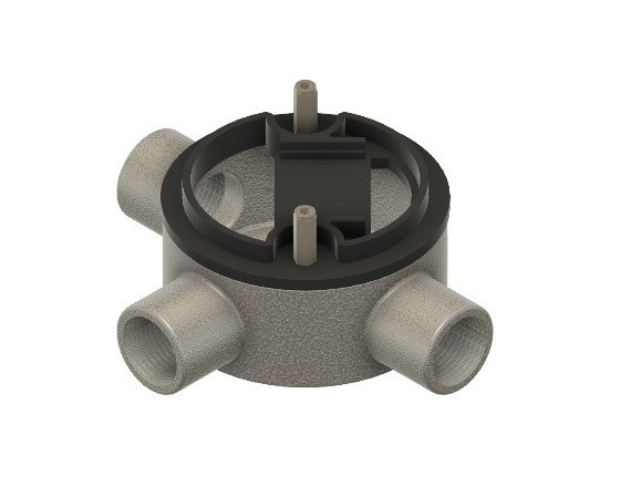
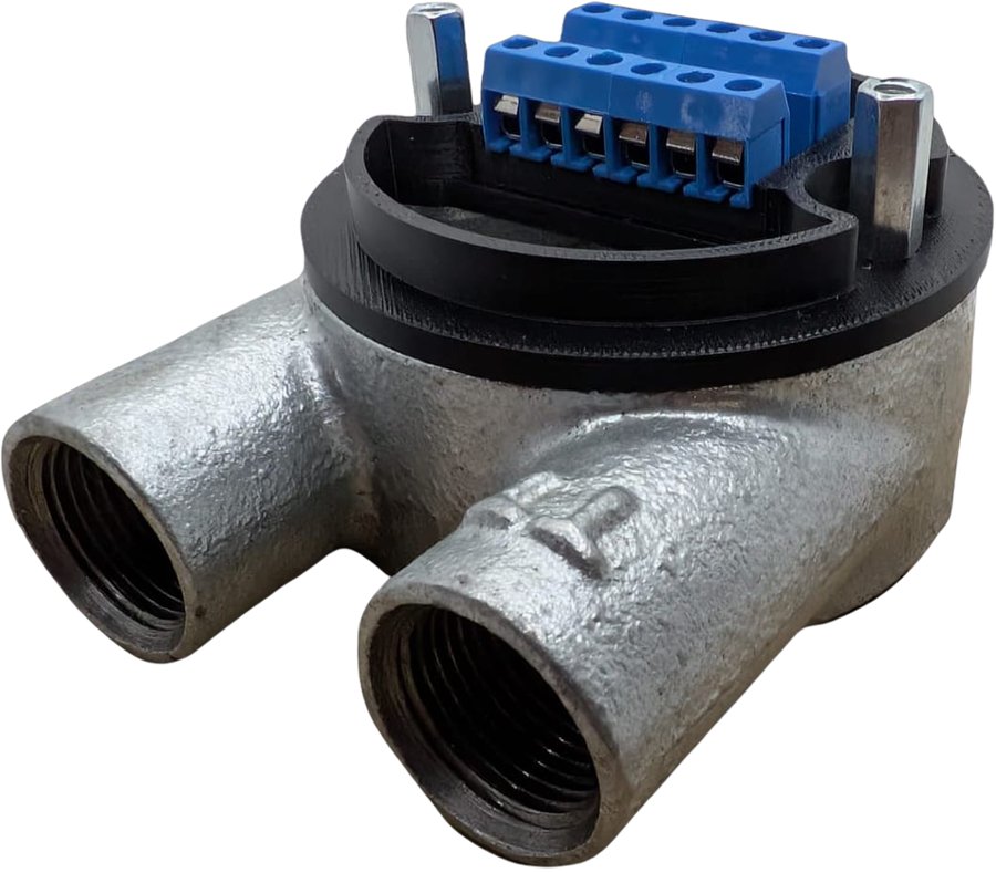
Seat the Tamper Insert on the conduit box and secure it with the two M4 standoffs.

Terminate the cable cores in the terminal block. Keep cores short and dressed inside the conduit box.
Connect the two tamper switch leads in series into the panel tamper circuit or a monitored zone. Fit end-of-line resistors of the value and configuration specified by the control panel manufacturer.

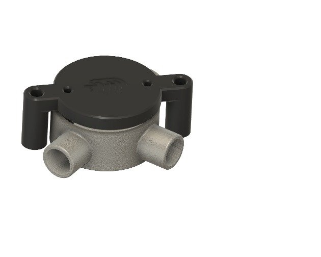
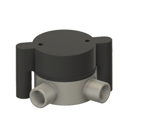
Lower the Main Body over the insert so the switches in the leg supports land on the screw heads. It should sit flush without force – if not, re-check step 2.
Secure with the two M4 × 16 mm security screws.
A 25 mm conduit box stands taller than a 20 mm box, so the Main Body legs will not reach the wall and the tamper screws must stand proud to reach the switch plungers.
No routine maintenance and no user-serviceable parts. At scheduled system maintenance confirm the fixings are tight, the body shows no cracks or deformation, and both tamper functions still operate (see the commissioning check).
| Model | T8-HSJB-STD (standard fixing). Adjustable-fixing variant: T8-HSJB-ADJ |
| Function | Tamper-monitored junction box for intruder detection, access control and CCTV field joints. Retrofits over an existing conduit box. |
| Tamper detection | 2 × switches: cover removal and removal from mounting surface. Wired in series (normally closed in the installed state) |
| Switch rating | 3 A 125 V AC / 1.5 A 250 V AC (momentary, SPST) |
| Terminal block | 12-point (4 × 3-way), 5.08 mm pitch, 12–26 AWG, 16 A / 300 V |
| Compatible boxes | Standard 20 mm and 25 mm conduit boxes (25 mm: fit the supplied leg extensions) |
| Fixings | 2 × 3.5 × 40 mm countersunk screws (supplied) with 5 mm or 7 mm collars. Wall plugs not supplied – select to suit the substrate |
| Security screws | 2 × M4 × 16 mm 6-lobe pin, pan head |
| Material / colour | ASA polymer (UV and impact resistant) · Black standard; white, grey, green and red to order |
| Environment | Indoor, dry, controlled environments. Not for corrosive, damp or external use. |
The HSJB is a passive mechanical component incorporating tamper detection switches and contains no active electronic circuits; it is outside the scope of UKCA/CE marking.
It has been independently tested, in the configuration described on this page, against BS EN 50131-3 tamper protection (8.7.1) and tamper detection on access to the housing (8.7.2.1) and removal from mounting (8.7.2.2) at Security Grade 3, Type B ancillary equipment; BS EN 62262 IK08; and BS EN 60529 IP40. Suitable for use in systems designed to comply with PD 6662:2017. Independent testing is not certification.
Overall system conformity remains the responsibility of the system designer or installer. Manufactured under the Tier8 Limited Quality Management System in accordance with ISO 9001 principles. Materials and fasteners are batch-traceable (see product label).
Questions during an install? Email orders@tier8.co.uk or call 01706 489765.
Page content matches installation sheet T8-HSJB-STD-IS · Rev 1.0 · September 2026